
Fiber Optic Splitters are very common in today’s fiber optic networks, There are 2 different kinds fiber optic splitters categorized by Product Technical. One is FBT fiber optic splitter and the other is PLC fiber splitter. To know their difference and charateristics better, We need walk into the world of How to Make Fiber Optic Splitter.
What is Fiber Optic Splitter
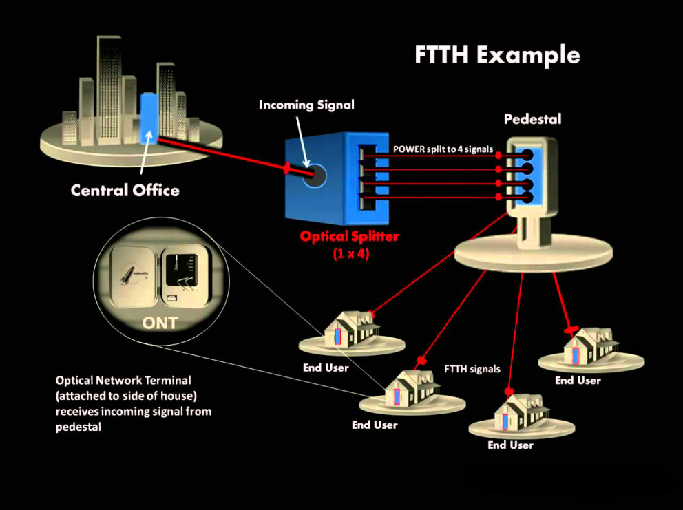
Before telling you how to make fiber optic splitter, you need to know what is fiber optic splitter first. A fiber optic splitter, also known as a beam splitter, is based on a quartz substrate of an integrated waveguide optical power distribution device, similar to a coaxial cable transmission system. The optical network system uses an optical signal coupled to the branch distribution. The fiber optic splitter is one of the most important passive devices in the optical fiber link. It is an optical fiber tandem device with many input and output terminals, especially applicable to a passive optical network (EPON, GPON, BPON, FTTX, FTTH etc.) to connect the MDF and the terminal equipment and to branch the optical signal.
How to Make Fiber Optic Splitter
Technologies used for constructing fiber optic couplers can be complex and difficult to understand. Two major manufacturing techniques
- Fused-fiber Optic splitter(FBT)
- Planar waveguide splitter(PLC)
How to Make FBT Fiber Optic Splitter
FBT is the traditional technology in which two fibers are placed closely together and fused together by applying heat while the assembly is being elongated and tapered. As the technology continues developing, the quality of FBT splitter is very good and they can be applied in a cost-effective way. Now FBT is designed to split power in optical telecommunication and widely used in passive networks, especially where the split configuration is relatively small.

How to Make (PLC) Planar waveguides Splitter
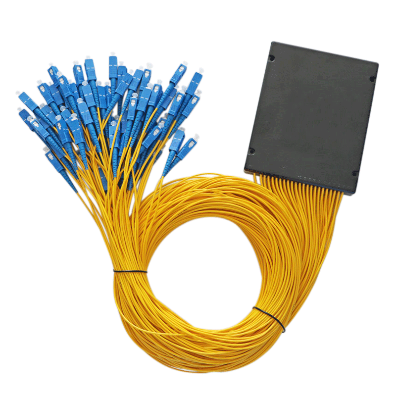
With the growth of FTTx worldwide, in order to serve mass subscribers, the demand for large split configurations in these networks has also grown quickly. Because of the performance benefits and overall low cost, PLC splitters are now the better solutions for these types of applications.
.png)