How to well understand performance of a FBT fiber splitter and PLC optic splitters? The first important thing is to discover its Fiber Optic Splitter Insertion Loss Table. This is the basic parameters should be archived. This Fiber Optic Splitter Insertion Loss is the splitter devices loss, Considering fiber connectors or connectors+adapter insertion loss in LGX, The fiber splitter IL would be a little bigger.
Brief Introduction to Optical Splitters
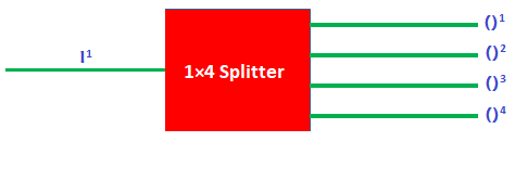
Optical splitters, including FBT (Fused Biconical Taper) couplers and PLC (Planar Lightwave Circuit) splitters, are common passive optical devices that split the fiber optic light into several parts by a certain ratio. For example, a splitter with 1×2 certain ratio configuration means that it has one input and two outputs. Likewise, there are 1×4 splitter, 1×8 splitter, 1×16 splitter, 1×32 splitter, and so on. When the splitter has two inputs and four outputs, it is called 2×4 splitter. Optical splitters play an important role in FTTH (Fiber to the Home) networks by allowing a single PON network interface to be shared among many customers. The following picture shows an optical splitter used in a PON system.
Optical insertion loss
The optical splitter is the component with the largest attenuation in a PON system. The optical insertion loss is the loss of an optical signal resulting from the insertion of a component such as connector or splice in an optical fiber system. In order to conserve the power budget of a PON system, the insertion loss from the splitter needs to be minimized.
Insertion loss testing of optical splitter is very important to ensure compliance to the optical parameters of the manufactured splitter in accordance to the GR-1209 CORE specification. Here is a table of typical losses for splitters. Signal loss within a system is expressed using the decibel (dB) which is a measure of signal power attenuation.
| Splitter Ratio |
Ideal Loss / Port (dB) |
Excess Loss (dB, max) |
Typical Loss (dB) |
| 1:2 fiber splitter |
3 |
1 |
4 |
| 1:4 fiber optic splitter |
6 |
1 |
7 |
| 1:8 optical splitter |
9 |
2 |
11 |
| 1:16 optic fiber splitter |
12 |
3 |
15 |
| 1:32 optic splitter |
15 |
4 |
19 |
Note:
1.Excess loss is the ratio of the optical power launched at the input port of the splitter to the total optical power measured from all output ports. It assures that the total output is never as high as the input.
2.Insertion loss is the ratio of the optical power launched at the given input port of the splitter to the optical power from any single output port. The insertion loss includes the splitting loss and excess loss.
How to calculate the maximum allowable insertion
The maximum allowable insertion loss for an optical splitter used in a PON system can be determined by using the calculations outlined in the below table.
| The maximum allowable insertion loss |
| 1×N Optical Splitter |
0.8 + 3.4 log2N |
| 2×N Optical Splitter |
1.0 + 3.4 log2N |
| Note: ‘N’ denotes the number of output ports. |
Temperature Dependent Loss
In certain areas, temperature can be a crucial factor that affects the insertion loss of optical components. FBT splitter can work stable under the temperature of -5 to 75℃. PLC splitter can work at a wider temperature range of -40 to 85 ℃, providing relatively good performance in the areas of extreme climate.
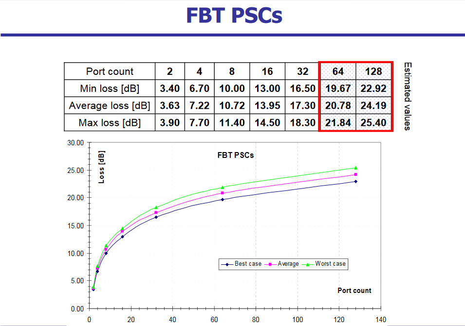
Fiber Optic Splitter Insertion Loss Table Reference for FBT and PLC types


.png)